- 您现在的位置:买卖IC网 > Sheet目录1198 > BG2A-NFH (Powerex Inc)KIT DEV BOARD FOR IGBT
�� �
�
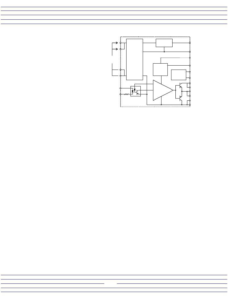
�series� hybrid� gate� driver� is� shown� for� reference�
�in� Figure� 1.� The� VLA500-01� and� VLA500K-01R�
�use� a� standard� high� speed� open� collector� type�
�Figure� 1:� VLA500� Series� Block� Diagram�
�opto-coupler� with� a� maximum� turn-off�
�propagation� delay� of� 1.3μs.� This� makes� it�
�1�
�+� 2�
�Regulator�
�16.4� VDC�
�19�
�V� CC�
�recommended� for� use� with� Powerex� NF-Series�
�-� 4�
�than� 20kHz.� The� VLA502-01� is� recommended�
�for� use� with� Powerex� NFH-Series� IGBT� modules.� Control� +�
�Input�
�For� additional� detailed� information� on� the�
�-�
�7�
�suitable� for� industrial� applications� with� operating�
�frequencies� of� up� to� 20kHz.� The� VLA500-01� is�
�and� A-Series� IGBT� modules.� The� VLA502-01�
�uses� a� high� speed� buffered� output� type� opto-� 3�
�coupler� which� provides� a� maximum� propagation�
�delay� of� 0.7μs.� This� makes� it� suitable� for� use� in�
�high� frequency� applications� operating� at� more�
�operation� of� the� hybrid� gate� drivers� please� see�
�the� individual� data� sheets.�
�A� complete� schematic� and� component�
�V� D�
�15V�
�5V�
�6�
�7�
�DC-DC�
�Converter�
�V� iso� =�
�2500V� RMS�
�180� ?�
�Opto� Coupler�
�Fault�
�Latch� and�
�Timer�
�Interface�
�Buffer�
�V� GE�
�Detector�
�20�
�GND�
�27� Shut� down�
�speed� Adj.�
�28�
�Fault�
�29�
�t� trip� Adjust�
�30�
�V� CE� detect�
�25�
�26�
�5�
�23�
�24� V� O�
�21�
�22�
�V� EE�
�selection� guide� for� the� BG2A� is� shown� in� Figure�
�2.� The� board� will� normally� be� operated� with� two� input� voltage� sources.� A� 5V� logic� source� (+V� L� )� provides� drive�
�for� the� high� speed� opto-couplers� inside� the� hybrid� gate� drivers� and� pull-up� voltage� for� the� fault� signal� isolation�
�optos� OP1� and� OP2.� A� 15V� power� supply� (+V� S� )� provides� power� for� the� gate� driver� and� is� connected� to� the�
�primary� side� of� the� hybrid� gate� driver’s� built� in� DC� to� DC� converter� at� pins� 1,2� and� 3,4.� The� +15V� source� is�
�decoupled� with� the� low� impedance� electrolytic� capacitor� C1.� In� the� BG2A� circuit� a� 1000μF� capacitor� was�
�selected� for� C1� so� that� the� same� capacitor� could� be� used� for� C1,� C2,� C3,� C5� and� C6.� In� most� applications� this�
�will� be� much� larger� than� necessary� to� support� the� drivers� ripple� current.� Typical� applications� will� be� able� to� use�
�100μF� or� less� depending� on� the� load� current� and� the� distance� from� the� main� 15V� supply� filter� capacitors.� The�
�hybrid’s� built� in� DC� to� DC� converter� provides� isolated� gate� drive� power� which� consists� of� +16.4V� (V� CC� )� at� pin� 19�
�and� -9V� (V� EE� )� at� pins� 21� and� 22.� These� supplies� share� a� common� ground� at� pin� 20.� The� gate� drive� power�
�supplies� are� decoupled� using� the� low� impedance� electrolytic� capacitors� C2,� C3,� C5� and� C6.� It� is� very� important�
�that� these� capacitors� have� low� enough� impedance� and� sufficient� ripple� current� capability� to� provide� the� required�
�high� current� gate� drive� pulses.� The� 1000μF� capacitors� used� on� the� BG2A� are� sized� to� supply� 12A� gate� pulses�
�at� a� 20kHz� rate.� If� the� application� is� operating� at� lower� frequency� or� lower� peak� current� it� may� be� possible� to�
�reduce� the� size� of� these� capacitors.� Consult� the� hybrid� gate� driver� individual� data� sheets� for� details� on� selecting�
�the� decoupling� capacitors.�
�The� V� EE� and� V� CC� supplies� are� connected� to� the� drivers� output� stage� to� produce� gate� drive� at� pins� 23� and�
�24.� The� gate� drive� current� is� adjusted� by� selecting� the� appropriate� series� gate� resistance� (R� G� ).� R� G� will� normally�
�be� adjusted� to� provide� suitable� drive� for� the� module� being� used.� For� more� information� see� Powerex� IGBT�
�module� application� notes.� Protection� against� gate� voltage� surges� is� provided� by� DZ2,� DZ3,� DZ5,� and� DZ6.�
�These� zener� diodes� also� help� to� control� short� circuit� currents� by� shunting� miller� current� away� from� the� gate.�
�Short� circuit� protection� is� provided� by� means� of� desaturation� detection.� For� details� on� the� operation� of�
�this� circuit� consult� the� specific� data� sheet.� The� collector� voltage� of� each� IGBT� is� detected� through� the� series�
�connected� high� voltage� blocking� diodes� D1,� D2� and� D3,� D4.� The� combined� blocking� voltage� of� the� series�
�connected� diodes� must� be� equal� to� or� greater� than� the� V� CES� rating� of� the� IGBT.� For� applications� using� lower�
�voltage� devices� it� may� be� possible� to� use� a� single� detection� diode.� DZ1� and� DZ4� protect� the� gate� driver’s� detect�
�input� (Pin� 30)� from� voltage� surges� during� reverse� recovery� of� the� high� voltage� blocking� diodes.� The� CS� and� CT�
�capacitors� are� used� to� adjust� the� drivers� protection� circuit� trip� time� and� slow� shut-down� speed.� The� driver� ’� s�
�default� settings� are� sufficient� for� many� applications� and� therefore� these� capacitors� can� be� omitted.� For� details�
�on� the� use� of� CT� and� CS� consult� the� specific� data� sheet.�
�If� th� e� gate� driver’s� short� circuit� protection� is� activated� it� immediately� shuts� down� the� gate� drive� and� pulls�
�pin� 28� low� to� indicate� a� fault.� Current� flows� from� Vcc� (pin� 19)� through� the� LED� in� fault� isolation� opto� (OP1,� OP2)�
�to� pin� 28.� The� transistor� in� the� fault� isolation� opto� turns� on� and� pulls� the� fault� signal� line� (FO)� at� pin� 4� of� CN1� low.�
�This� opto� isolated� signal� can� now� be� used� by� the� controller� to� detect� the� fault� condition.�
�Interface� Circuit� Requirements:� A� typical� interface� circuit� for� the� BG2A� is� shown� in� Figure� 3.� A� single� +15V�
�control� power� supply� (+V� S� )� is� connected� to� pin� 5� of� CN1� with� its� ground� at� pin� 6.� This� supply� provides� all� of� the�
�2�
�发布紧急采购,3分钟左右您将得到回复。
相关PDF资料
BG2B-5015
KIT DEV BOARD 2CN 5A FOR IGBT
BG2C-5015
KIT DEV BOARD 5A FOR IGBT
BH-0111
FUSEBLOCK 1 HOLE #1 STUD SIZE
BJ150
TRS BLKHD PUSH-ON JACK STR SLD
BJ157F-2C
TRS BULKHD JACK STR FLNG SLD POT
BJ157
TRS BLKHD JACK STR FRONT MT SLD
BJ21
BNC BLKHD CABLE JACK 50 OHM STR
BJ27
BNC BULKHEAD JACK 50 OHM STR SLD
相关代理商/技术参数
BG2B
制造商:Powerex Power Semiconductors 功能描述:GATE DRIVER 制造商:Powerex, Inc. 功能描述:BG2B Board Is A Bare PCB Only
BG2B020
制造商:Siemens 功能描述:
BG2B-1515
功能描述:KIT DEV BOARD 1.5A FOR IGBT RoHS:否 类别:编程器,开发系统 >> 评估演示板和套件 系列:- 标准包装:1 系列:PCI Express® (PCIe) 主要目的:接口,收发器,PCI Express 嵌入式:- 已用 IC / 零件:DS80PCI800 主要属性:- 次要属性:- 已供物品:板
BG2B-3015
功能描述:KIT DEV BOARD 2CN 3A FOR IGBT RoHS:否 类别:编程器,开发系统 >> 评估演示板和套件 系列:- 标准包装:1 系列:PCI Express® (PCIe) 主要目的:接口,收发器,PCI Express 嵌入式:- 已用 IC / 零件:DS80PCI800 主要属性:- 次要属性:- 已供物品:板
BG2B-5015
功能描述:KIT DEV BOARD 2CN 5A FOR IGBT RoHS:否 类别:编程器,开发系统 >> 评估演示板和套件 系列:- 标准包装:1 系列:PCI Express® (PCIe) 主要目的:接口,收发器,PCI Express 嵌入式:- 已用 IC / 零件:DS80PCI800 主要属性:- 次要属性:- 已供物品:板
BG2B-F
制造商:Powerex Power Semiconductors 功能描述:KIT DEVELOPMENT ACCY GATE DVR 制造商:Powerex Power Semiconductors 功能描述:DEV KIT, M57145L-01, M57160AL-01, WITH BARE PCB; Silicon Manufacturer:Powerex; Silicon Core Number:BG1A-KA; Kit Application Type:Driver - Transistor; Application Sub Type:IGBT Gate Driver; Leaded Process Compatible:No ;RoHS Compliant: No 制造商:Powerex Power Semiconductors 功能描述:GATE DRIVER
BG2C
制造商:Powerex Power Semiconductors 功能描述:GATE DRIVER
BG2C-3015
功能描述:KIT DEV BOARD 3A FOR IGBT RoHS:否 类别:编程器,开发系统 >> 评估演示板和套件 系列:- 标准包装:1 系列:PCI Express® (PCIe) 主要目的:接口,收发器,PCI Express 嵌入式:- 已用 IC / 零件:DS80PCI800 主要属性:- 次要属性:- 已供物品:板